Simple Sound Schematic
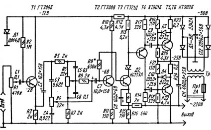
On the basis of this diagram, you can build a sound plug that can develop a good output power with good sound quality. With a minimum number of radios in the force, which allows it to be assembled by a hanger even a starter.
Only three transistors and a handful of capacitors are used in the scheme. Output power sound energy is 18 wt on load 8 Om or up to 30 wt on load 4 Om. The ratio of non-linear distortions is relatively small - 0.8 per cent, which is typical of the transistor type of audible force. To guarantee full stability sound Frequencies, we need to adjust the power supply. Inprincipe, this is not a problem, since the audible actor requires only a single polar power source. The sound level and the stiffness of the transducer shall be reduced and the required output power per load shall be provided. The power source shall be calculated for at least 2 amper and an average voltage of 40 volts.
Radios used in sound energy diagram:
R1=2, 2 kOm 0, 25 W
R2=27 kOm 0, 25 W
R3, R4=2, 2 kOm 0, 5 W metallic or carbon (or 2 kOm)
R5=100 Om 0, 25 W
R6=1 kOm 0, 25 W
R7, R8=330 Om 0, 25 W
C1=22 mkF 25 V
C2=47 pF 63 In ceramic
C3, C4=100 umF 50 In electricity
C5=2200 mkF 50 V
Q1=BC550C 45 100 mA Transistor n-p-n structure
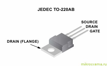
Q2=IRF530 100 V 14 A N-can field tranchist (or MTP12N10)
Q3=IRF9530 100 V 12 A P-can field tranchist (or MTP12P10)
Now elaborate on the main radio components of the audible surgeon. There are two powerful field transistors out.
IRF530:
Share this Post
Related posts
How To Make A Sound Surgeon
Todays audio system is a large number of different devices, instruments and tools. It is not hard to understand that their…
Read More
Connection Of The Music Centre To Tv
Music Center, TV, transition cord. Instruction of devices. Looking closely at the TV and the music center, you ll notice…
Read More


