Microphone Shoe
 This article describes my high-quality microphone rapist. Initially, it was designed to be applied in an electric capacitor microphone capsule couple, but the high characteristics and characteristics of the scheme allow it to be used with practically any microphone and to obtain excellent results for both measurement and sound recording. Why didn't I take one of the many schemes available online? Because they all have one big flaw, and that's what they look like to each other, like twins, about it.
1. Critics of the standard diagram.
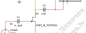
We'll see the pattern in the documentation for the electric capsules used in all the devices I've seen.
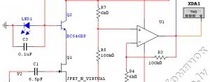
There's a C1 condenser and a field transistor here, that's what's inside the capsule, R1 rubber, external load, and XDA1 and XSC1 modules are simulator tools, Oscillographer and heater. The analysis shows that strengthening this scheme is negative! I mean, on the way out of this scheme, we have a signal about 8dB weaker than he was on the hood membrane! Which means that the signal should be increased more than once in the future, which means that the noises made will be higher. It is not enough that the inclusion of a field transistor in itself gives very large non-linear distortions, at the input level indicated on the scheme, they exceed 1 per cent. And despite this, all the authors of the rapists continue to use this, which is a good one for schoolchildren to learn the basics of the electronics scheme! And that makes the sources of stable power to feed the capsule on the ooh, what they're trying to do is not understandable. I didn't get it right, so I designed my scheme.
There is another option for further refinement, as proposed on LinkwitzLab. It is proposed to change the design of a built-in field transistor with a common origin scheme to the original repeater scheme. This shows an increase in the overloading capacity of the capsule (in a general velocity diagram, the output voltage reaches very quickly the amplitude limits, i.e. these limits are very small - about +-1B) and also a sharp reduction in non-linear distortions, i.e. not reaching the amplitude limits, the signal is severely distorted. I've experienced this addition, but it's not, however, out of the way to the standard scheme, but it's still a very small improvement - I thought there was a need for a major improvement in the system!
2. What can I do?
On the basis of this, I have taken a cascoding scheme for the following reasons:
It creates constant tension in the field tranzistor, which dramatically reduces its incontinence.
Share this Post
Related posts

How Do You Make A Phone Plug
Do you need to buy a gadget when there is room for a device collected from hand-held equipment? Those who have at least initial…
Read More
How Do You Make A Cologne Booster
Many people would like to have an audio system 5.1 at home, but for the frequent price of such a force, it s pretty big…
Read More


