Sound Frequency Power

Introduction
Good afternoon, esteemed Habrauser, I'd like to tell you about the foundations of a sound frequency booster. I think this article will be interesting to you if you've never done radio electronics, and of course it'll be funny to someone who doesn't break up with a peanut. So I'll try to tell you about this topic as simple as possible and regrettably lower some nuances.Sound booster Frequency or low-frequency escalator to understand how it works and why there are so many transistors, receptors and condensators, we need to figure out how each element works and how these elements are built. We're gonna need three types of electronic elements to collect the primitive vigilator, the capacitors, and of course the transistors.
Rezist
So we have electrocutors, and this resistance is measured in Omaha. Every electrical conductive metal or metal alloy has a specific resistance. If we take a wire of a certain long with a great resistance, we'll be able to have the most real procrastinator. To make the storyteller compact, the wire can be wet on the carcas. So we're gonna have a wireless statistician, but he's got a number of flaws, so the cutting agents are usually made of metal causal material. That's how the electrocutors are identified:The upper version of the symbol is accepted in the United States, the lower in Russia and Europe.
Condensator
The condenser represents two metal plates divided by dielectric. If we put a constant strain on these plates, there will be an electrical field that, once the power has been disconnected, will maintain a positive and negative charge on the plates, respectively.Condenser structure is based on two conductive linings between which the dielectricity is located
So the condenser can accumulate the electrical charge. This power to accumulate the electrical charge is called the electrical receptacle, which is the main capacitor parameter. The electrical capacity is measured in Faradach. What's different is that when we load or unload the condenser, it's electric.
 But as soon as the condenser's loaded, it stops running the electric current, which is because the condenser has taken the charge of the power source, that is, the condenser and the power source are the same, and if there is no difference in capacity (pressures), there is no electrical current. Thus, the loaded condenser does not pass the constant electrical current, but it passes the variable current, because when it is connected to the variable electrical current, it will be loaded and discharged continuously. On electrical circuits, it is defined as:
Transistor
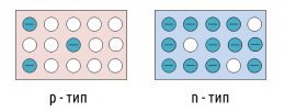
In our ass, we will use the simplest bipolar tranches. The transistor is made of semiconductor material. The material we need is the presence of free bearers of both positive and negative charges. Depending on which charges are greater, semiconductors distinguish between two types of conductivity: -type and -type (n-negative, p-positive). Negative charges are electrons released from the outer casings of crystal bars atoms and positives are so-called holes. The woods are vacant seats left in electronic casings after the electrons left. Symbol minus sign atoms with an electron in the outer orbit, empty circumference:Each bipolar tranzist consists of three areas of such semiconductors, the zones call the base, the emitter and the collector.
Let's look at the tranzistor's work. To this end, we'll connect two batteries to the tranzistor at 1, 5 and 5 volts, plus the emitter, and minus to the base and the collector, respectively (see figure):
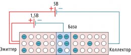 The base and the emitter will have an electromagnetic field that literally rips the electrons off the outside orbit of the base atoms and moves them to the emitter. Free electrons leave holes behind and take vacant seats in the emitter. The electromagnetic field has the same effect on the collaborator atoms, and since the tranzistor base is sufficiently thin about the emitter and the collector, the electrons of the collaborator are easily passed through it to the emitter, and much more than the base.
If we turn the pressure off the base, there will be no electromagnetic field, and the base will act as a dielectric, and the tranzistor will be closed. So when we put enough pressure on the base, we can control the higher voltage on the emitter and the collector.
We've got a tranzistor pnp-type, because he has two ozones and one ozone. There are also npn-transistors, the principle of action in them is the same, but the electric current in them is the opposite of the tranzistor we have considered. That's how bipolar tranches are marked on electrical circuits, the shooter indicates the direction of the current:
NIS
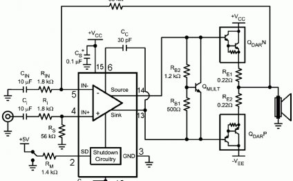
Well, let's try designing this whole low frequency escalator. For starters, we need a signal that we're gonna reinforce, it could be a computer sound card or any other sound device with a linear exit. Let's say our signal with a maximum amplitude of about 0, 5 volts with a current of 0, 2 A, about:And what would be the simplest four-wheeled 10-vatt dynamics, we need to increase the amplitude of the signal to 6 volts, with current = U / R = 6 / 4 = 1, 5 A.
So, let's try to connect our signal to the transistor. Remember our tranzistor and two batteries, now instead of one, five volt batteries, we have a linear exit signal. The R1 Reissor is a load so that there is no short circuit, and our transistor is not burned.
But there are two problems here, first of all, our transistor npn-type, and only opens with a positive semi-volume and closes negatively.
Share this Post
Related posts
How To Make A Sound Surgeon
Todays audio system is a large number of different devices, instruments and tools. It is not hard to understand that their…
Read More
Review Of Music Centres
Even if you re not a meloman, the music center in your house has the right to exist. Cause good music in a great sound can…
Read More


